TETRAHEDRAL INFILL SOLIDS

This project follows a previous project I did using Processing, where I scripted a space frame that randomly assembled itself, analyzed its structural integrity at each frame, and fell apart. The space frame recorded most fit generations and used those as a starting point, allowing the program to 'evolve.'
This project starts with the single tetrahedral frame and attempts to create manipulable and unique geometries within, as determined by the geometry of the tetrahedron.

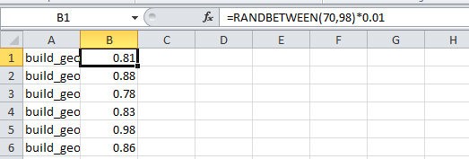
The four surfaces of the tetrahedron each host a closed spline, tangent and coincident with each edge. A parameter drives the position that the spline is coincident with the edge, thereby driving the overall spline. An inner spline is also computed as coincident with lines from the vertices to the face center point, generally varying between ratios of .7 and .98.

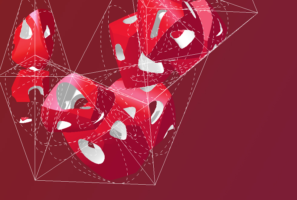
Each outer spline is extruded normal to itself, and intersected with the others to form the infill solid. Each inner spline is then extruded to cut holes from the solid.


The result is a solid whose form depends both on the overall shape of the tetrahedron, and on the points determining the inner and outer splines. As the tetrahedron height changes, the infill solid morphs and expresses different geometric conditions.

The tetrahedron and infill can be multiplied as a powercopy. When each successive instantiation is built upon the previous, all tetrahedrons are interdependent: when a single tetrahedron's shape changes, all following tetrahedrons will deform, causing their infills to be modified. In this animation, the simple change in tetrahedron height changes every single instantiation every frame.
It is also worth noting that the assembly tends to normalize over successive generations. While the first (stationary) tetrahedron is fairly irregular, the following instantiations trend towards being a regular tetrahedron.

The difficulty in the string of tetrahedrons is the ever-increasing chance of breaking the geometry. Errors such as the one below seemed to result from the solid operations required to form the infill solids. These errors made it difficult to get the above animation, though I would have liked to show a much greater range of motion.

I also took the parameters into tables where the values were randomized, resulting in some pretty strange assemblies.
SOLIDS:
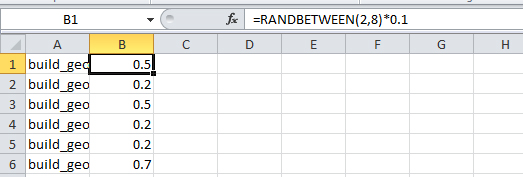
HOLES: